


The size of my original article on Tiger II V2 got a little out of hand. To keep the length down, the section with a comprehensive background on Tiger II tracks is published here as a separate article for the tech-savvy readers.
Being a test vehicle, it is not surprising that Tiger II V2 covered many test kilometres. The observations made during testing were used to improve the Tiger II and set in motion all kinds of changes and developments. For example, all kinds of changes were made to the Tiger II’s tracks. In this article we will look at the developments the tracks went through and what made them so special in the first place.
Table of Contents
- Breaking new ground
- Legacy of the Panther II
- Elusive Designation
- Why Go Double?
- Trouble Maker
- On the Right Track
- Doubling Down on Single Links
- Bibliography
Breaking new ground
The tracks of the Tiger II were a complete departure from the usual German design. The Tiger II tracks consisted of so-called Doppelkettenglieder, double track links. According to the preliminary manual1, each double-track link incorporated the following parts:
- 1 bridge link [with two guide teeth]
- 1 intermediate link
- 3 side links, “as auxiliary links by means of joint bars”
- 2 track pins

It thus took both a bridge and intermediate link to form a single ‘main link’, a rather complex design. Furthermore, each intermediate or connecting link consisted of several parts. Since the connecting link itself was quite narrow, three side links were used to connect it to the bridge link.
With its 800 mm, the bridge link was rather wider than the connecting link. The bridge link formed the main contact to the ground, as it had two grousers (ground contact bars) with five chevrons on its face to improve grip. The bridge link provided two guide teeth for track control spaced 212 mm apart.
At first sight, both guide teeth appear to be the same length, but in fact the inner tooth is 10 mm shorter than its counterpart. Therefore, the outer guide is 100 mm, while the inner guide is 90 mm. It seems that the inner guide tooth was shortened due to space constraints at the drive and idler wheels. There are no such size restrictions for the outer tooth, which is why it was executed somewhat longer.

The track was designed by Ritscher-Moorburg (Moorburger Treckerwerke). This firm could fall back on years of experience of track design for various other Wehrmacht vehicles, among which were the Tiger I and various half-tracks2.
According to the tentative manual, there were 92 links per track, but the later official D-Vorschrift for the driver states a total of 90. The sprocket of the drive wheel was of such pitch that it engaged every link, and it had 18 teeth. The initial Geländekette (cross-country track) described above was designated Gg 24/800/3003. Because of the double-link design, links could only be added or removed in pairs when the track had to be lengthened or shortened to adjust track tension.


The 800 mm wide combat track did, however, protrude beyond the allowed railway loading gauge. This meant the wagons would not clear all tunnels nor oncoming traffic. Therefore, a complementary 660 mm wide Verladekette (transport track) was available, named Gg 24/660/300. This track was originally intended as combat track of the Panther II1, but this vehicle never entered series production.

Legacy of the Panther II
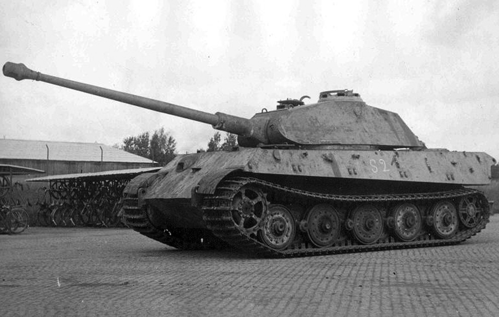
The origin of the double track links can be traced back to the Panther II, which was in development around the same time as the Tiger II. In early 1943, an attempted unification with MAN’s Panther II was initiated by Wa Prüf 6/III. Much to the dismay of Henschel’s designers, many Panther parts had to be incorporated into their design4. The rubber-saving steel wheels designed for the Panther II also found their way into the Tiger II design.
A quick peek at Tiger II drawing number “021 C 49505-U2” for the Laufrad (roadwheel) learns us that the wheel was indeed originally designed for the Panther II as indicated by its drawing number “021 D 50204” – which falls in the series reserved for the Panther II 5. The steel wheels were first fitted to Panther chassis number V1, along with a new type of track and a modified 20-teeth sprocket. Panther V1 underwent testing with these wheels on June 29, 1943 at the Märzfeld Wellenbahn.


The track on V1 deserves our attention: it was apparently specially designed for use with the new steel wheels and, unlike stated by Macdougall and Neely6, is actually distinct from the later “Gg 24” track used on the Panther II – or Tiger II for that matter. The number of pin lugs differs from the final version (both in number and width). In addition, the bridge link is more robust with thicker guide teeth with three vertical reinforcing ribs. Furthermore, the chevrons on the track surface and the rectangular reinforcement pattern are arranged differently.


It is noteworthy that the use of steel wheels apparently went hand in hand with double-link tracks. The combination of the two was also proposed for the Panther (I), but apparently never materialized. On January 4, 1944, this was discussed: “This new track is to consist of a cast link with one guide tooth and two cleats and a forged Zwischenglied (connecting link). Due to the low number needed, it would be better to cast this Zwischenglied.”7
Elusive Designation
The official designation of the double-link tracks is somewhat problematic. The prefix “Gg” does not adhere to the general three-letter system used to explain a track’s properties. Witthuhn, author of “Die Sohlen der Tiger”, gives the explanation that the first letter G could mean the track is experimental8, which is rather unconvincing. In “Panzerketten”, Schwarzmann poses a more plausible explanation in which “Gg” would be used to indicate materials: G for Gußstahl (cast iron bridge link) and g for geschmiedet (forged connecting link)9.
The designation “Gg” is not unique to the Tiger II tracks. To my knowledge, it is found on one other vehicle, namely the schwerer Wehrmachtsschlepper (sWS). The tracks for this vehicle, like those on the Tiger II, consist of a bridge and intermediate link. The track designation for the sWS is Gg 25/500/180, indicating a width of 500 mm and a pitch of 180 mm. In appearance, these tracks are very similar to the second generation of Tiger II track: Gg 26/800/300.

Why Go Double?
When confronted with the unusual track design, Allied intelligence could only guess the reason for using two link types. They noted, “the reasons for the German employment of two types of track link are difficult to assess”10. They reasoned that with such a heavy vehicle, one link would probably should be laterally strong and therefore feature two grousers. It was also suggested the placement of the track pin lugs opposite of each other, would better conduct stresses and benefit track strength.
“Some decided benefits must be obtained in order to justify the use of two forms of track link”
The same report praised the suspension and track design for its excellent track control characteristics: “there are no less than fifteen guide horn under the control of the bogie wheels. It will be appreciated that steering, and particularly skid steering, is very much facilitated by this arrangement.” The report concluded that “In any case, some decided benefits must be obtained in order to justify the use of two forms of track link”10.
And indeed, according to the Germans, there were distinct advantages to the novel track making the effort worthwhile. Reasons underlying the unconventional design included its desired material properties as well as the wish to obtain a standardized track. Henschel’s chief designer Edwin Aders explains in his 1945 memorandum:
“The desire to manufacture at least part of the links by forging, as well as to create a uniform track for the right and left side, without different running resistances, led to a track with cast links with guide teeth for track control and a drop forged, though presently also cast, connecting link consisting of multiple parts”
Aders, “Die Tigertypen E Und B: Entstehung Und Entwicklung.” [translation by author]
An advantage of forging is that the end product is stronger than when cast or machined. The forged connecting links are easily recognizable by their smooth-textured surface. With very early variants, the joint bars appear to have been forged as well. However, after some time connecting links started being cast from Manganese steel, just like the bridge link. From that point forward, both link types had a rectangular pattern on their track face for added strength.
Furthermore, the problem of a distinct left and right track was never solved satisfactorily for the Tiger I4. The fact that there were two links in use, which were in-fact mirror images of each other, made for a logistical nightmare. This problem was “solved” by abolishing dedicated tracks for either side as of the 21st Tiger I (October 1942)11.


Left: the left track runs in the intended direction: sprocket teeth pull at the strongest part of the track.
Right: The right side runs in reverse and the sprocket pulls on the track pin lugs.
In practice, this meant the left track was fitted on the right side as well, albeit in reverse. Problem solved? Not really, as this had a major drawback; because one track ran forward and the other in reverse, the tracks wore differently resulting in unequal rolling resistance12. This would could cause the tank to pull to one side by itself, requiring constant course adjustments. The cleverly conceived two-piece link design eliminated all of these problems while still allowing the use of an asymmetric link.
Trouble Maker
On paper, the double-link track was the perfect solution. However, the first teething problems soon came to light during an inspection of the first prototype Tiger II, chassis No. V1, in December 1943. Without prior testing, the head of Henschel’s proving ground at Haustenbeck-Lippe, Kurt Arnoldt, noticed many potential problems with the design13. In his opinion, the track had little sideways stability compared to that of the Tiger I.

He foresaw that after uneven wear of the connector’s side links, the track could bend, in some cases causing the links to pull and push on each other. In that scenario, the guide teeth would start to “restlessly” wander from left to right and rub against the rims of the bogie wheels – more so than on the Tiger I.
Furthermore, the angular design of the guide teeth appeared unfavourable. Arnoldt said this could cause problems, especially at the point where the teeth pass in-between the bogie wheels. It was further noted that snow or sand could settle on notches in the guide teeth with the necessary consequences.
In relation to this, Aders remarked that the tolerance between the bogie wheel and guide tooth position, which at the urging of the Heereswaffenamt14 had been reduced to just 2 mm, was far too small. Aders concluded that the track was too “loose” and therefore had little resistance to torsion.


Return of the Track Pin (Plate)
And that wasn’t all. Arnoldt noted that it would be wise to install a Kettenabweiser (track pin return plate), just to be on the safe side13. A track pin return plate pushes back track pins that work their way loose and prevents them from falling out, disconnecting the track links – or worse. The Soviet T-34 is notorious for its use of a pin return plate as the sole measure to secure its track pins. While return plates also found their use in German designs, such as the Tiger I and Panther, their tracks were first and foremost secured using rings with dowel pins.
Arnoldt recognized that with the tracks now positioned even closer to the hull side than on the Tiger I, the danger of bending or breaking track pins was even greater. Aders agreed and expressed himself as follows regarding the issue:
“The new type of track showed, to an even greater extent than with the Tiger E, the disruptive property that the pins wander in the direction of the hull, where they catch on the backside and break.”
Aders, “Die Tigertypen E Und B: Entstehung Und Entwicklung.” [translation by author]
Seeing that Aders still complained about the issue of wandering track pins in February 1945, the problem must have remained insufficiently solved. This is remarkable, all the more since Arnoldt stated in December 1943 that the use of a return plate was foreseen and trials would commence shortly. So what happened during these tests, if these were performed at all?
Unfortunately, the source material at hand does not reveal anything about testing of a return plate at Haustenbeck. There is, however, evidence of troop trials with the schwere Panzer-Abteilung 506 in September 1944. At the end of the month, the unit reported on their combat experiences. They were issued with 12 mm thick return plates, which were to be welded to the hull side15. The writer of the report notes the plate was still far from perfect, inhibiting normal installation and operation of the transport tracks. Due to the decreased clearance to the hull side of only 8 mm, the transport track would only fit with the idler set to its foremost position. This did, however, lead to problems with track tensioning.
“2) Kettenabweiser still imperfect, currently made of 12 mm sheet steel that must be welded to the side of the hull. However, the distance between the transport track and the hull is only 8 mm. For installation of the transport track and driving with the transport track the idler had to be set to the foremost position. By doing this, the transport track became too long again, however, after taking out one link it was too short. (…)”
sPzAbt 506 / Abt. Ia/V(K), “Erfahrungen Mit Dem Panzerkampfwagen ‘Tiger’ B.” [translation by author]

I cannot say for sure whether other Tiger IIs were ever fitted with a track return plate, but it seems unlikely such a plate was ever adopted on a large scale. Neither the few chassis where the rear most section of the hull is or was unobstructed (Full Reuenthal after sandblast or TWC) nor the raw steel armour hulls that were still at the assembly line in 1945 show clear sings of a return plate.
Worse for wear
Subsequent test drives brought yet another issue to light. After a test with V2 on March 17, 1944, it became evident that every second sprocket tooth was badly worn. This occurred after driving only 804 km16. After measuring several links, it turned out that they were of uneven pitch. Due to manufacturing imprecisions, the pitch of connecting links was up to 10 mm larger than that of bridge links. This caused the former to rub against the drive teeth with the necessary abrasion as a result, literally carving out the sprocket teeth.


Another problem that arose was the track’s tendency to climb onto the sprocket. It was not clear whether this was caused by the track’s “looseness” or the aforementioned uneven pitch4. Arnoldt later claimed the only solution was to use longer guide teeth, but there is no evidence of a design attempt with such a feature17.

Possibly, longer sprocket teeth would also have alleviated the tendency for track-jumping. A drawing of a redesigned sprocket ring was dated 30 July 1944. This appears to have been created in reaction to one of Arnoldt’s statements from 1943: “It cannot be excluded that the sprocket tooth is too short. Experiments are still being carried out in this regard.”13 The improved sprocket was finally introduced in March 1945, but more about that later.
On the Right Track
To remedy the most serious problems with the original track, an alternative design was introduced in May 194418. The Gg 26/800/300 track was not as flexible as the previous design. Now only bridge links engaged with a 9-teeth sprocket and the one-piece connecting links better resisted sideways motion. The sprocket ring had a stepped outline, with slight indentation to accommodate the connector links wrapping around the drive wheel.

A drawback of this design was that the load was distributed over a reduced number of sprocket teeth. This caused excessive wear on the remaining 9 teeth. According to an Allied report, the driving sprockets on a number of examined vehicles were “very badly worn after what would be considered a small amount of running”10. The Soviets commented similarly on the issue in their October 1944 Bulletin of the Tank Industry: “This design of the track led to a sharp reduction in the number of teeth on the drive wheel and, as a consequence, to their rapid failure”19.

On November 4, 1944, Thomale, chief of staff Generalinspekteur der Panzertruppen, briefed Hitler on complaints of the troops regarding the Tiger II. “These complaints”, he said, “could be traced back to the new track, which, although a considerable production simplification, on the other hand entails a greater susceptibility of the Tiger”20. The engagement of only every second sprocket tooth was causing “sudden jerks in the final drive, which cannot withstand these blows”. Thomale announced that a new track was on its way, for which all the sprocket teeth engaged with the track again.
At several occasions in early 1945, Thomale took a stance against the, in his eyes, exaggerated production simplifications that were carried out at any cost. According to him, prime examples were the Panther final drives and Tiger II tracks, which led to increased losses and expenditure in material and man power to fix the problems created by the initial simplification21.
Doubling Down on Single Links
To overcome the existing problems, the unsuccessful double-link design was reconsidered. A new single-link design, Kgs 73/800/152, was introduced, accompanied by the reintroduction of an 18-teeth sprocket. As the design was asymmetrical, there were again mirrored left and right-handed tracks. The design is reminiscent of the Tiger I’s Kgs 63/725/130 track with trapezoid-shaped partitions on its surface. The new link also had openings for the installation of two Hammerstollen, an accessory to improve grip on frozen surfaces9.


According to Spielberger, the single-link track was introduced as early as November 194422. At this time, work on an improved track was first revealed to Hitler, who hoped that it would be ready for use by the schwere SS Panzer-Abteilung 50120. Instead, the new track was first employed on a few Tigers delivered to the schwere Panzer-Abteilung 506 that took part in the Battle of the Bulge. These Tigers were also equipped with the initial 18-teeth sprocket.
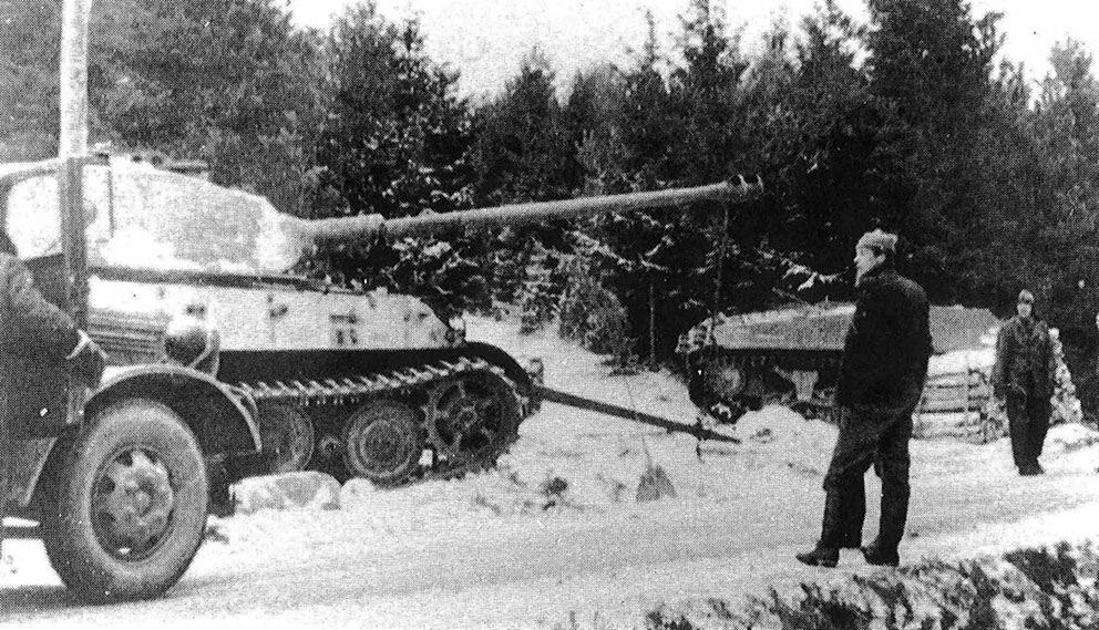
The “Kgs 73” was not mounted on a large scale until March 194523. However, at that time many Tigers were delivered to the troops on transport tracks. It seems that, due to the deteriorating war situation and the approaching front, inadequate quantities of the new tracks were able to reach the assembly line at Kassel-Mittelfeld. The photo below supposedly shows piles of Kgs 73/800/152 tracks, stranded at Paderborn station, some 100 km from Kassel24.


Coinciding with the introduction of the new track, a new 18-teeth sprocket, with longer, pointier teeth was introduced25. The 18 sprocket teeth were 1.5 mm longer and 3 mm thicker than before. Ostensibly, this sprocket solved the problem of excessive wear – both by increasing the number and thickness of teeth.
It was doubted whether the “Kgs 73” was actually used in the field, as adoption started only just before the assembly line was overrun. Nowadays, there is enough photographic evidence to corroborate this type of track was used on a couple of Tigers from sPzAbt 507 and 510/511. A CIOS investigation team also confirmed there were Tigers on the assembly line with single-link tracks17.


Cliffhanger
With the introduction of the single-link track, several changes to the turret were also being introduced. One of the changes was an updated arrangement of the spare track hangers on the turret sides. Instead of the original four sets of hangers on either side, the updated turrets disposed of six sets of hangers23. Every pair of hangers would accommodate a single link. This modification was not very widespread, and photos from the Henschel plant show turrets with both the updated and original hanger pattern awaiting installation.

Based on the hangers, which appear identical all round the turret, it may be concluded that only the left-hand tracks were to be used in the field26. If this is correct, it can be assumed that, as with the Tiger I, it was decided to drop the right-hand links altogether. In the small selection of photos of Tiger IIs with the Kgs 73 track, in which the track direction is recognizable, it appears that a left track is indeed fitted on the right side.


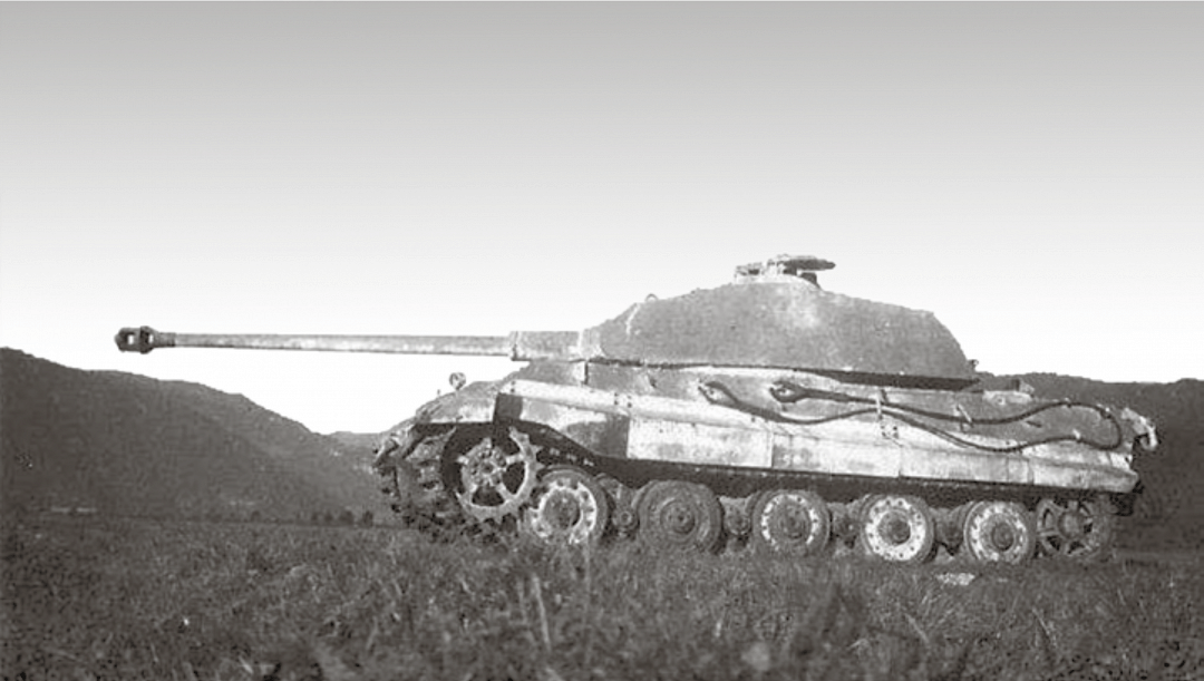
After the war, two test vehicles with the single-link tracks were found by the Allies. Both sported left and right track links. Chassis No. 280 006, aka V6, was found at the Heereswaffenamt’s winter test facility in St. Johann. This vehicle was sold to Sweden in 1947 and used for various tests. It was shot-up during the 50s and besides its engine and transmission, only one hatch remains of it27. The other vehicle was chassis No. 280 009/12 at Henschel’s Panzerversuchsstation 96 in Haustenbeck. At some point after the war, V2’s original Gg 24/800/300 tracks swapped for the latter vehicle’s single-link tracks. This makes V2 the only Tiger II left today with this type of track.


Following are more detail shots of the Kgs 73/800/152 track as seen on V2 today. The chevrons are worn down quite a bit. Miraculously, the left and right tracks on V2 have been fitted correctly.


Bibliography
Footnotes
- Henschel u. Sohn, “Sammelmappe Für Panzerkampfwagen Tiger B.”[↩][↩]
- Spielberger, Die Motorisierung Der Deutschen Reichswehr : 1920-1935., Weede, “Zurück Zu Den Wurzeln.”[↩]
- first digits are a design identifier, while the last two explain themselves as follows: 800 mm wide, pitch of 2 * 150 mm = 300 mm[↩]
- Aders, “Die Tigertypen E Und B: Entstehung Und Entwicklung.”[↩][↩][↩]
- Drawing numbers 021 Gr 50201 through 021 Gr 50248[↩]
- Macdougall and Neely, Nürnberg’s Panzer Factory : A Photographic Study.[↩]
- Jentz and Doyle, Panzer Tracts 5-4, Panzerkampfwagen Panther II and Panther Ausfuehrung F.[↩]
- Witthuhn, Die Sohlen Der Tiger. Versuch Einer Katalogisierung Der Gleisketten Für Die Tiger-Panzer.[↩]
- Schwarzmann, Panzerketten : Die Gleisketten Der Deutschen Kettenfahrzeuge Des Zweiten Weltkrieges.[↩][↩]
- 21st Army Group, “A.F.V. Technical Report No. 17.”[↩][↩][↩]
- Jentz and Doyle, Germany’s Tiger Tanks : D.W. To Tiger I.[↩]
- Aders, “Die Tigertypen E Und B: Entstehung Und Entwicklung.”, Jentz, Doyle, and Sarson, Kingtiger Heavy Tank, 1942-45.[↩]
- Arnoldt, “Bericht Über: Auflegen Der Gefechtskette Beim Tiger B (Nr.245).”[↩][↩][↩]
- Specifically Referent Dipl-Ing. Köhler[↩]
- sPzAbt 506 / Abt. Ia/V(K), “Erfahrungen Mit Dem Panzerkampfwagen ‘Tiger’ B.”[↩]
- Arnoldt, “Bericht Über: Laufwerk Am Tiger B / v2 (Nr.269).”[↩]
- CIOS, “German Practice on Suspension and Running Gear for Tanks.”[↩][↩]
- Schwarzmann, Panzerketten : Die Gleisketten Der Deutschen Kettenfahrzeuge Des Zweiten Weltkrieges., Aders recalls this track was introduced in July 1944[↩]
- Сыч, “Новый немецкий тяжелый танк „Тигр В“.”[↩]
- Generalinspekteur der Panzertruppen / Chef des Stabes, “Notiz Zum Führervortrag.”[↩][↩]
- Generalinspekteur der Panzertruppen / Chef des Stabes, “Besprechung Mit Reichsminister Speer.”, RM.f.R.u.K. / Entwicklungskommission Panzer, “Bericht Über Die Vollsitzung Der Entwicklungskommission Panzer Am 23.1.1945.”[↩]
- Spielberger, Panzer vi Tiger Und Seine Abarten.[↩]
- Jentz and Doyle, Germany’s Tiger Tanks VK45.02 to Tiger II.[↩][↩]
- Ackermans, “Stockpile of Kgs 73/800/152 Geländekette at Paderborn.”[↩]
- Volgin, Panzerkampfwagen Tiger Ausf.B : Construction and Development.[↩]
- See Doyle’s drawings in Jentz and Doyle, Germany’s Tiger Tanks VK45.02 to Tiger II and the comments of Zrodlowski, “Tiger Ausf.B Final Production Tracks.”[↩]
- SPHF, “The Swedish King Tiger.”[↩]
Leave a Reply